
The Peugeot Boxer, Citroen Relay and Fiat Ducato can be equipped with an option for a “Conversion Interface” or Converter’s socket.
Fiat: “Electrical Interface Supply Socket (For Conversions)” option 081
Peugeot: “Electrical connections interface box / Includes reinforced alternator” option JI01
Citroen: “Conversion interface box”
These connections are intended for use by vehicle converters who wish to interface with the vehicle electrics. Even if these options are not specified on a new van, quite a few people have found the converter’s sockets installed anyway. The sockets offer a few things which may be of some use if you’re converting one of these vans:
- A switched 12V signal which is live when the ignition is on (KEY+)
- A charging signal (from which a D+ “charging” signal can be obtained)
- High current connections to the cab battery
- Rear speaker connections
All of these things can be picked up elsewhere, but the converter’s socket provides a convenient place to get these and one which hopefully won’t cause issues with the warranty on a new van (the main reason we had for specifying this option on our van).
The following isn’t official advice or definitive information – your van might be totally different! It’s just a summary of what I’ve found to be relevant to our van (a 2018 Citroen Relay). Please check carefully – I won’t be held responsible if something goes wrong!
The sockets are located at the bottom of the (UK) driver’s side ‘B’ pillar (next to the handbrake).
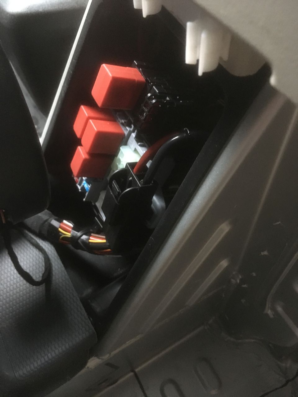
To find out if they are fitted, you need to remove the black trim from around the base of the ‘B’ pillar and see if the 3 sockets in the photo below are present:
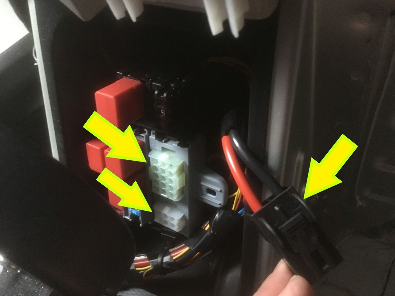
Battery connection
The large connector with the red and black wires is the feed from the vehicle battery. It’s connected to a dedicated 50 amp midi fuses on the battery positive terminal (so is permanently ‘live’). The Fiat Converter’s Manual rate this connection as ‘max constant current 53A’.
I used this socket as a supply to our 30 amp battery-to-battery charger.
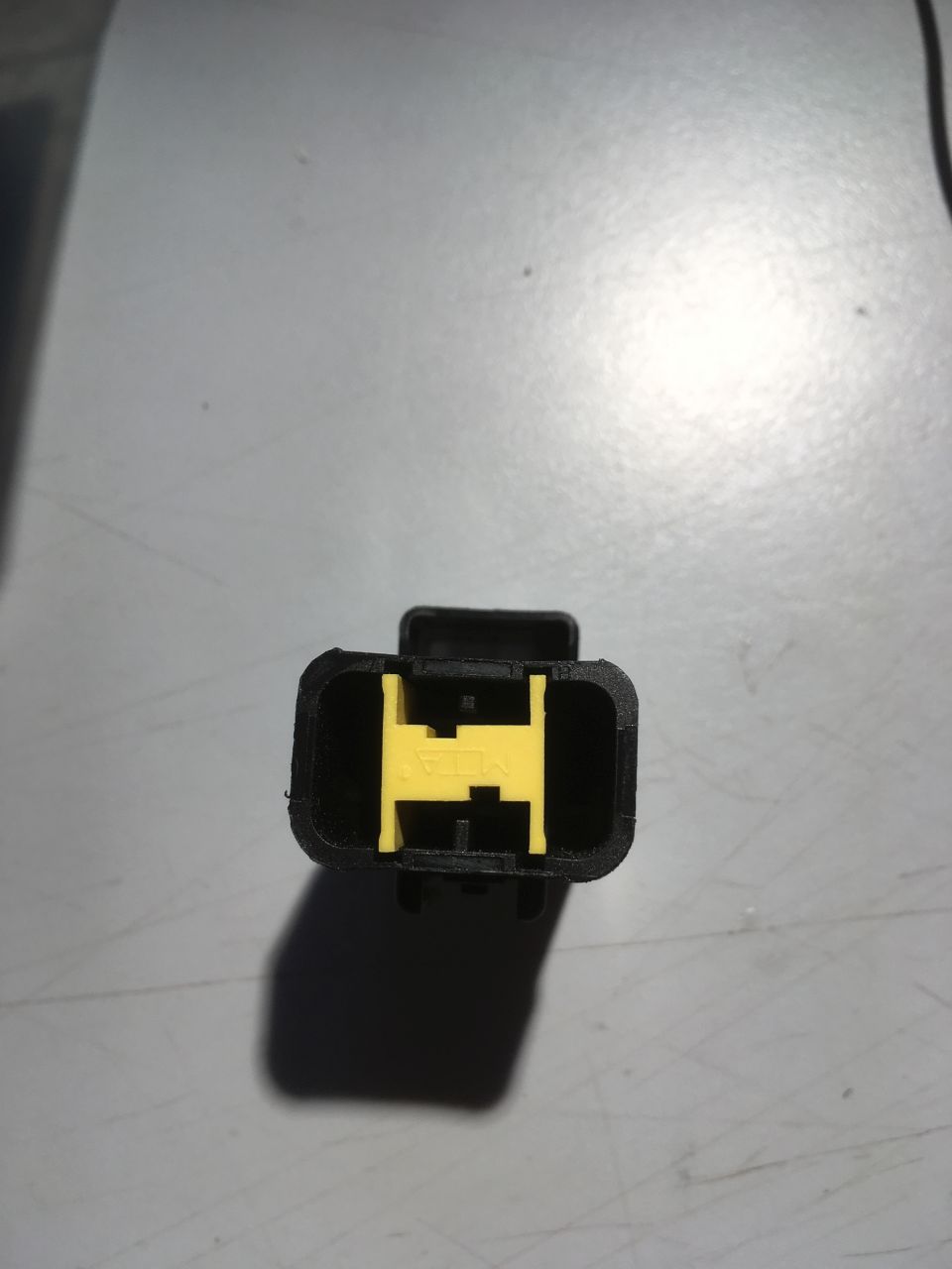
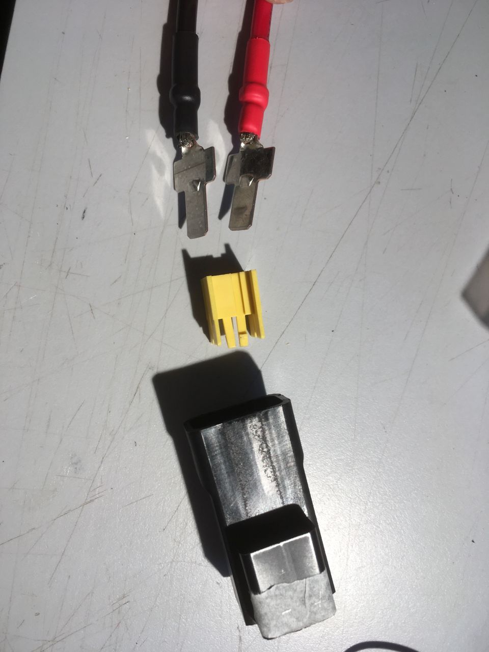
The mating plug (MTA 45.40400) is already fitted to the connector, but isn’t supplied with any contacts. (Press the clip and the two halves of the connector will separate.) You will need to find two contacts, part number MTA 1707685. (I found them on ebay with the description “TERMINAL KONTAKT VON MACHT MÄNNLICH MTA 1707685 AUTO CAMPER MOTORRAD AUTOMOBIL” – note that you will need two).
Once you have separated the two halves of the connector, the contact retainer unclips from the back of the plug:
The contacts
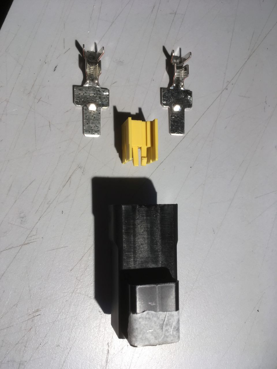
The contacts soldered to wires, insulated with heat shrink and ready to fit to the connector housing. Note that I’ve marked the + and – sides (on the masking tape) from the red and black wires fitted to the van side of the connector.
The terminals slide into slots in the connector
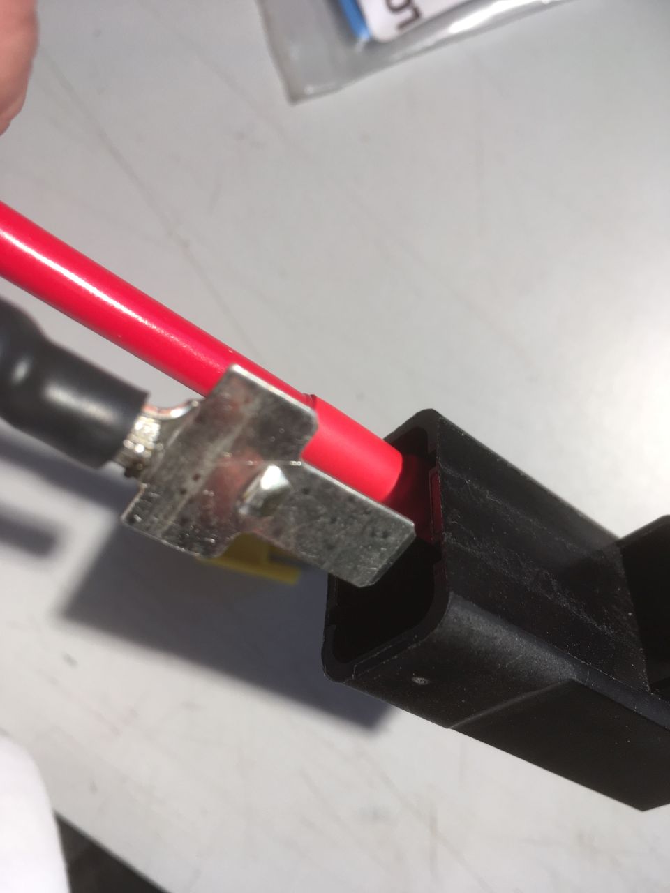
They’re held in by the yellow clip:
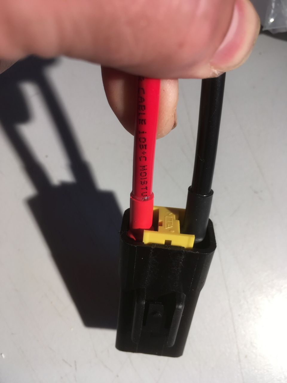
If everything is assembled correctly, the clip will latch home.
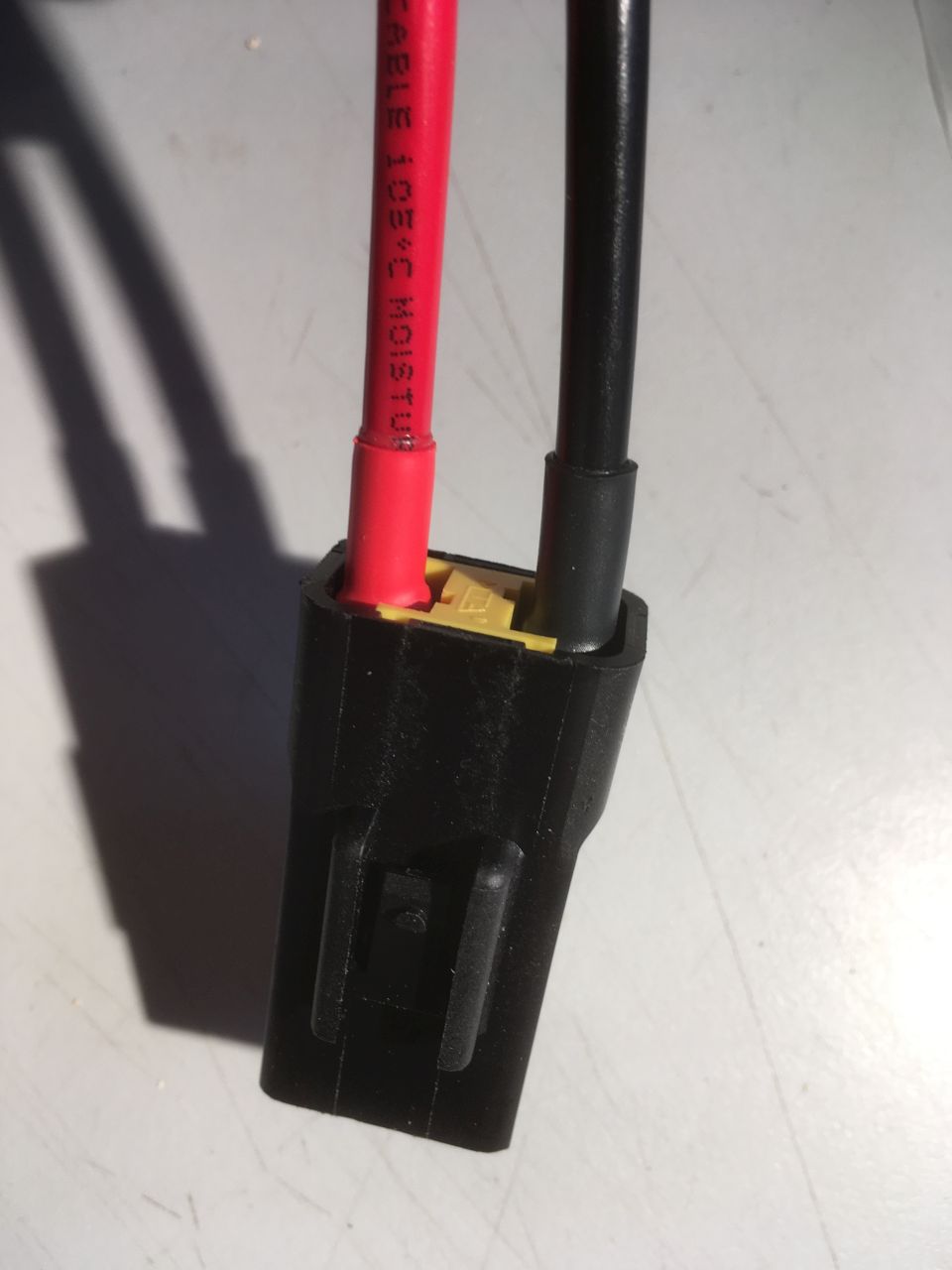
The other side:
The 15 way connector
The following information is what I could find for the current X290 series of vans. Colour codes aren’t necessarily consistent from year to year, or from manufacturer to manufacturer, so proceed with caution and satisfy yourselves that you’ve identified the correct pins.
The 15 way connector functions are described in the Fiat Converter’s Manual (X290 version):
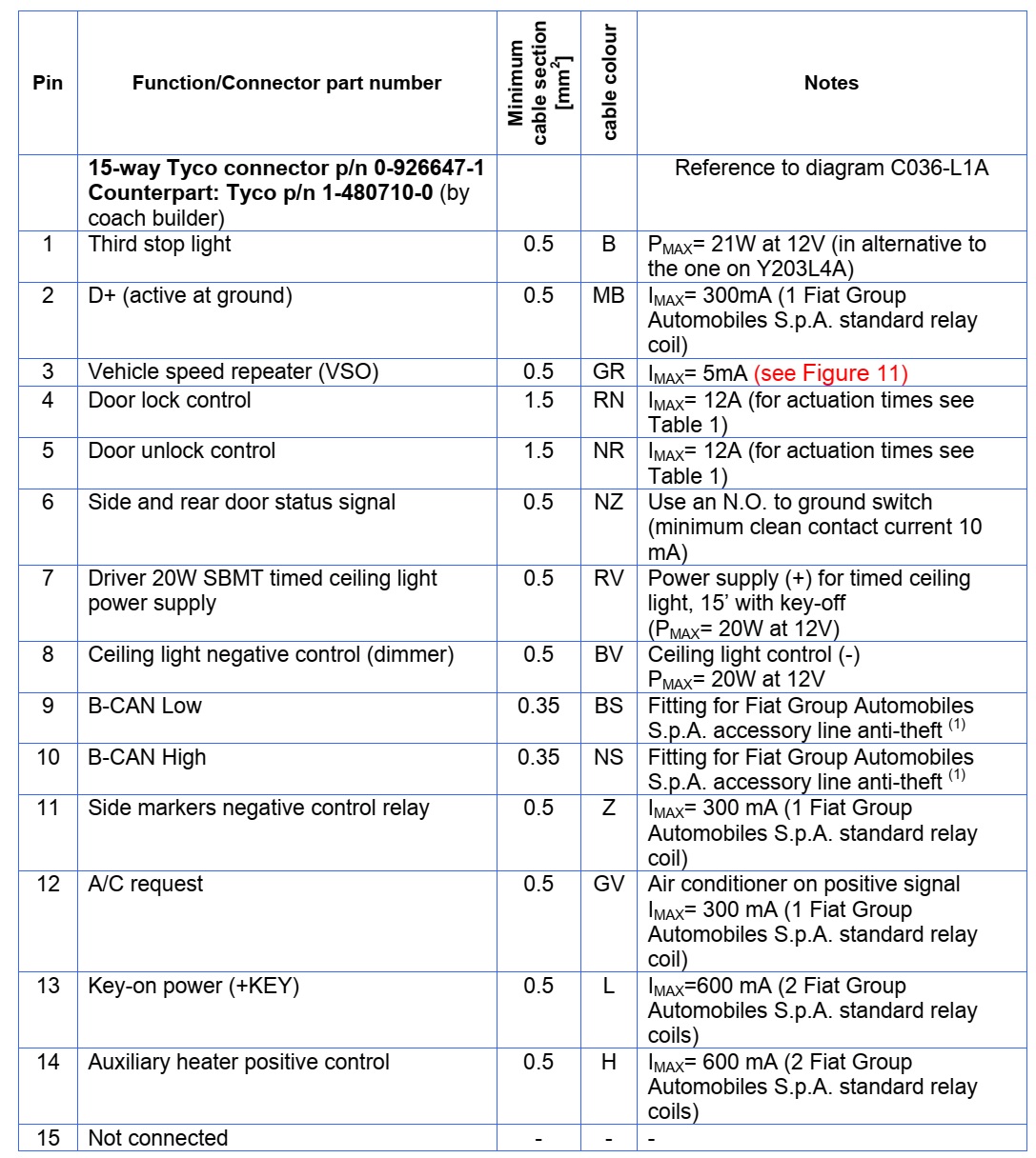
The mating connector for this socket isn’t supplied – it’s a Tyco ‘Mate’n’Lock’ 15 way plug part number 1-480710-0. You will also need some male connector pins to suit. Again, these are easily available from ebay
To confuse matters, there seem to be two different ways that the sockets have been numbered.
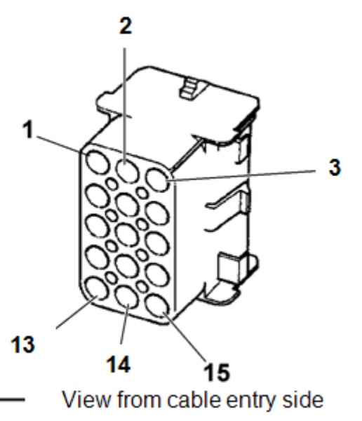
The Converter’s Manual shows the numbering as three columns of 5:
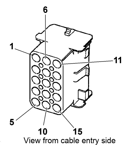
This was *not* how our van was wired. By tracing the wiring colours and doing some tests, I found that the table above was still correct, but that the pin numbering was arranged as five rows of three:
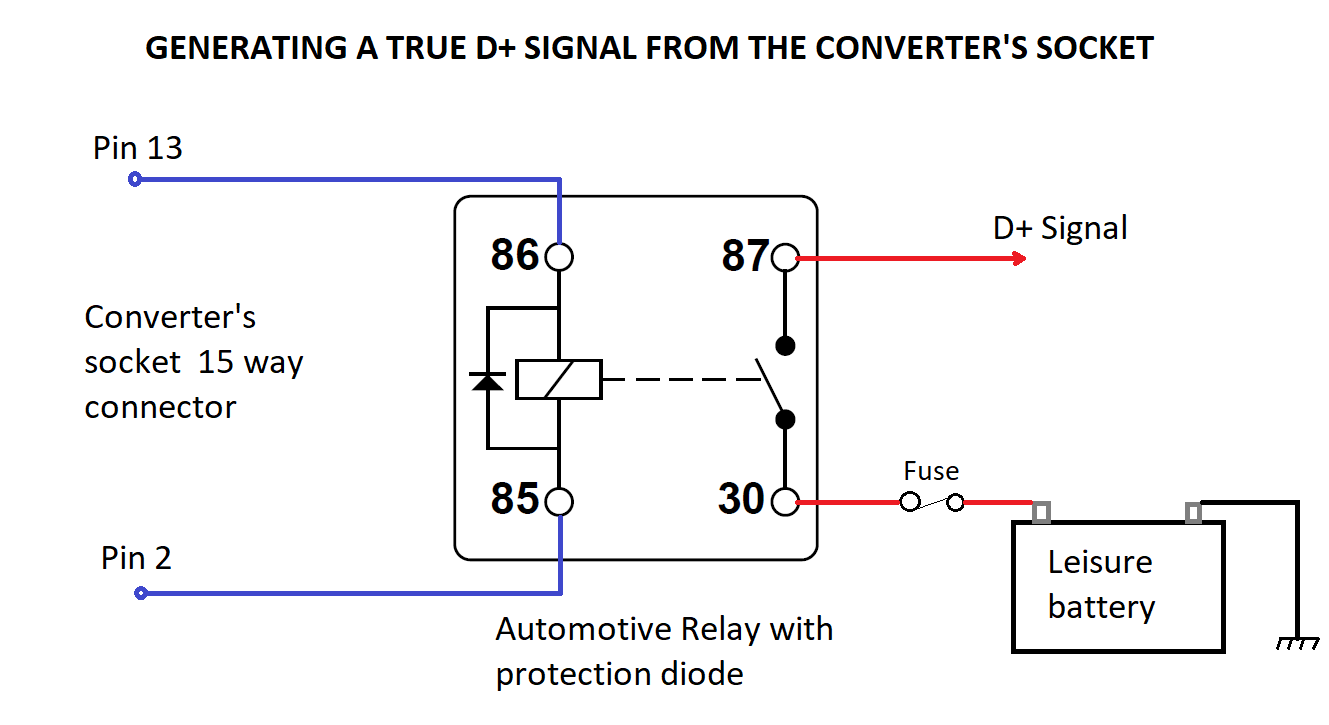
Check your socket carefully, as there’s no guarantee that Fiat et al haven’t come up with another way of numbering things in the meantime. The wiring colour codes are Italian, I think:
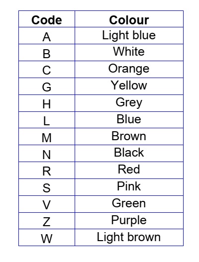
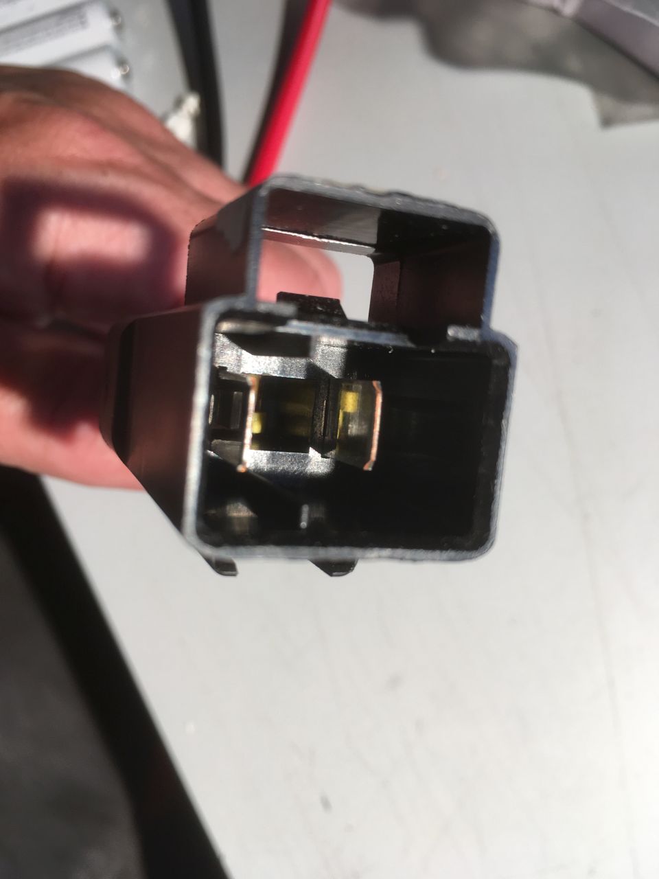
This is the rear of the socket in our van (a 2018 Relay) showing the wiring colours:
‘Key ON’ / B+ Signal
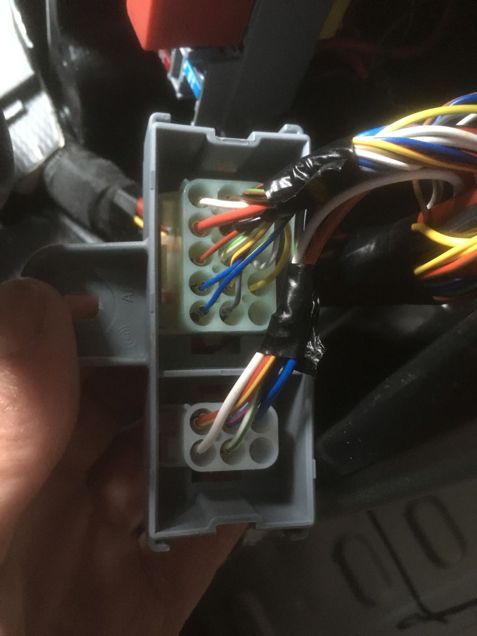
The “Key ON” signal is straightforward to get to on pin 13 – the two blue wires in the photo below. Note that this is only really intended for electronic signaling or powering a maximum of two relays.
D+ / Charging Signal
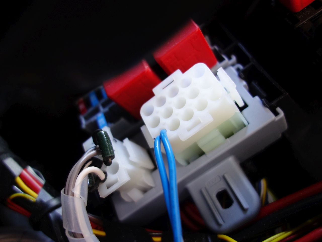
The D+ (‘Charging’) signal is not as straightforward: Pin 2 of the connector actually goes to ground when the alternator is charging, rather than to 12V like a true D+ signal.
In order to generate a true D+ signal it is necessary to wire a relay into the circuit: Relay pin 86 should be connected to pin 13 of the converter’s socket (+12V supply with limited current – suitable for 2 relays / 600mA max). Relay pin 85 should go to pin 2 of the converter’s socket (active low D+ signal). It is a sensible precaution to use a relay with a built in protection diode to reduce the risk of damage to the ECU.
The fuse is just sized to protect the D+ wiring and supply any loads on the D+ circuit.
The 12V for the D+ signal could come from pin 13 of the converter’s socket too (connect relay pins 30 and 86) if the loads are very low, and you are confident that the total load on pin 13 won’t exceed Fiat’s 600mA limit.
Rear Speaker Connections
These are on the 6 way connector:
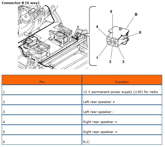
The mating connector is a TYCO ‘Mate’n’Lock’ 6 way plug part number 1-480704-0 with male pins to suit. (ebay
Note that pin 1 is described as ’12V permanent power supply…’ – this is just a connection back to the dashboard so that an after-market radio could be supplied by 12V from the leisure batteries via this connector. I believe that the wiring at the radio connector also needs to be modified to use this connection. Fiat do not allow this modification for the standard radio.
The stock ‘Uconnect’ radio may or may not have its rear channels enabled. Ours did, but the head unit also needs to sense a load on the speaker terminals to actually make the rear channel live.
As I just wanted to connect a subwoofer to the rear channels, I had to add dummy load resistors to the connector (you can see one in the Key+ picture above). I used 56 ohm, 3W wire-wound resistors, but I’m sure you could buy something suitable from a car audio shop.
There are various instructions on how to enable the rear channels, but this option may not be present. Even though it relates to the US Promaster van, the menus, etc. from page 7 onwards of this document (pdf) are present our head unit, but like I say, the rear channels were already enabled when we got the van.
Thank you so much. This is super helpful!
Thank you very much! Glad you found it useful 😊
does anyone know why there is a fuse missing right next to the top relay? my one keeps blowing
I don’t, I’m sorry.
Thank you for the correct pin-out diagram. I had the incorrect diagram from Fiat, and wasted a large part of my day with a mulitimeter failing to work it out for myself. Your information was invaluable.
No problem! I’m pleased that it has been of use to someone. It was a bit of detective work to get there – the information is all out there somewhere, just not all in the same place. Good luck with your build, and thank you very much!
Thank you so much for this and sharing it has been most helpful. What amp relay should I use for D+ 30 or 40 amp?
Hi, thanks for the feedback! 🙂 Assuming that you’re looking at standard automotive relays, either would be fine (the relay is only carrying a few milli amps). Get one with a built-in protection diode though.
Me again. Sorry. What size wire do I require for the relay to converters socket. Will 1mm 16.5amp do? Also as I note ppl are asking about smart alternators. Mines a 2021 relay with smart alternator. Anything with a euro6 engine that came out of Sevel has a smart alternator. Also how are you doing with your build Mister?
Excellent article thank you!
One thing I want to sanity check before I try this.
The red cable obviously goes to the positive terminal on the leisure battery. Is the black cable coming from the negative terminal on the leisure battery as well? Essentially is this what is being used for the ground?
Thank you and sorry if a stupid question
Hi, thank you for the complement! 🙂
I’m not 100% sure which picture you’re referring to – is it the wiring for the relay?
If so, the negative / ground for the relay coil comes from pin 2 of the 15 way connector – this is the signal that Fiat/Citroen/Peugeot provide.
Provided that the leisure battery negative is connected to the van body at some point (the usual arrangement), there is no need for a separate ground for the D+ signal.
HTH – if not, please post again and I’ll try and help.
Sorry yes my question wasn’t clear. I was referring to the battery to battery connector at the top of the article.
As I’m placing my leisure battery at the rear of the van can I just ground at the back of the van or do I need to connect the ground through this connector like you have this article,
Thanks again
Ahhh! OK – this one the red cable *comes from* the *vehicle* battery – the connection needs to go to a split charge relay or battery to battery charger which, in turn, would then go to the leisure battery.
The black lead is the factory provided ground/negative. It just connects to the metalwork somewhere in the cab area. I used it for convenience – there’s no need to use this if you don’t want to – just connect to a substantial piece of van metalwork as you’re suggesting.
I’m trying to find this on a 2016 Peugeot Boxer. Before conversion it was a delivery van so I suspect it isn’t fitted, but am unclear about the location as the photos are close up. The B pillar has two sides, one next to the drivers seat, the other in what would have been the van body before the convertors got their tin snips out. Any clarification would be appreciated. If the socket isn’t fitted where else is it possible to pickup the D+?
The convertor has fitted a fridge behind the B pillar so while possible it’s extremely difficult to take the cover off there, hence the question
Hi,
The opening in the ‘B’ pillar faces the driver’s seat, and would be in the cab of a van with a bulkhead. It’s underneath the cover next to the handbrake, below the seatbelt reel. There should be some electrical connectors and relays there, even if the converter’s socket isn’t fitted. It’s the one secured by the two screws in this photo .
I haven’t really investigated where else to get a D+ signal (I haven’t needed to!), but I have seen references to the need to splice into the loom somewhere neat the ECU. I can’t vouch for these though. You may be able to use an ignition switched signal (“Key+”) instead of D+ which would be easy to pick up using a ‘piggyback’ fuse holder on an appropriate fuse in the main fuse box by driver’s right knee. (Try the third fuse from the right in the top row, but please check for yourself).
Good luck! 🙂
Hi. That very good article and it is the only guidance that is available. Thank you so very much! We also bought conversion socket and are about to start our electric work on our build ( exciting time). Do you know if your van has a smart alternator ( our is 2021 boxer)? The Reason i am asking is that our B2B charger requires D+ for smart alternators. And if that is the case would it mean that i can not use the Battery connection, but will need to get D+ from 15 way connector?
Hi, Thank you very much! 🙂
Our van is 2018 and does not have a smart alternator. The 2021 vans may have a smart alternator – I don’t know for sure. The D+ signal is only to turn the B2B on and off, you will still need that battery connection in addition to the D+. There is no “real” D+ signal on the 15 way connector – you would need to use a relay to generate one as shown above. Alternatively, you could use the “key+” signal that *is* on the 15 way connector. The difference is that D+ is only active when the engine is running, but the Key+ is active all the time that the ignition key is on (and, anecdotally,*may* stay active for ~15 mins if the key is left in the ignition after switching off). Hopefully that makes sense – if not, please let me know!
Hi 🙂
That wire sounds fine. Our van is 2018 euro6, but not smart alternator (I believe that those equipped with start-stop would have had smart alternators). Newer vans may well have smart alternators regardless.
Build is done! 🙂 I really need to get my ass in gear and update the website!
Thanks. Forgot to mention start stop. Thanks for your article and all your help. It’s all in a working as it should, thanks to you sharing that bit of knowledge. It’s saved me a whole load of hastle. Much appreciated. Yeah please update be interested to see.
Hi,
Very interesting article!
Thanks
Mine is a 2019 relay, euro 6 enterprise model. Any idea if mine as a smart alternator or any advice on now to find out?
I want to use a spilt charge relay that I already have!
Thanks
Matt
Hi,
I’m not really sure about your van. Does it have stop/start? If so, I think it will have a smart alternator.
Hi again. We are proud to say that your instruction work perfectly and we now have B2B connection via the interface box. thank you. our next challenge is to connect dash cam via the 15 way connector. our dash cam should use less than 1000mA. what I am not clear from above instruction is where do I connect Camera`s positive and negative cables to? do they go to relay and if so which #? your support is much appreciated
Oh, sorry – I missed this!
There isn’t enough power available from the 15 way connector to provide 1000 mA directly, so you will need a relay of some sort. If you already have the D+ signal with a relay as per the diagram above, you can use the same connection to power the dashcam (provided you are happy for it only to be powered while the engine is running): Positive of the Dashcam would go to D+ (#87 on the relay), negative would go to any ground connection.
Sorry for the delay, and thanks for the thanks 🙂
I connected a dashcam at the front and picked up power from the Head unit feed witha piggy back connector. It comes on with the engine which is how I wanted it and it seems to be working fine. It seems simpler that running a cable all the way to the converter’s socket. Hope this is OK to do. I have not got my head round how relays work yet – too advanced for me but will try to educate myself more when I connect the PMS – haven’t had the van go up in flames since connecting the dash cam so thats a good sign I guess, haha
Sounds fine to me! I’d only bother with the Converter’s socket for stuff in the back of the van (like camper electrics) to save running wires forward to the battery / dash.
Thanks so much for taking the time to share all the info and pictures. I have tried to connect the rear speakers but no sound coming out. I tested my (aftermarket) headunit and confirm rear speakers are powered. Do I need to do anything to ‘activate’ the rear speaker connection from the back of the headunit to the b pillar plug? Also, it seems the rear speaker colours in the B pillar do not mucg the ones coming up behind the head unit. Any ideas please?
Hi,
As far as I know, the 6 way plug in the B pillar is ‘hardwired’ through to the head unit connector (I think there may be an intermediate connector in the dash where the wire colours could change).
This is the pinout I have for the original Uconnect head unit, and the colour codes do, indeed, look different to the ones on the 6 way connector.
https://uploads.disquscdn.com/images/127922f052ee2ff3715c777e657cdc41d84a2fd456ac32ca5e5d5ce74c0718fc.jpg
If you have the original head unit, you may need to actvate the speaker outputs (and it will need to detect a load on them before it will activate them), but as you have an aftermarket unit (if I have understood correctly), there shouldn’t be anything else to do.
There is a factory option of ‘preparation for radio’ (or something similar) which removes the canbus integration to ease the fitting of an aftermarket radio – it’s possible that the connector wiring could be different in that case (I would expect it to be a standard connector though) – you can tell if you have this option as it will be possible to set the date/time using the ‘mode’ switch on the dash.
Thank you for such a quick and detailed response. Yes it is an aftermarket unit and I have already tested the rear speaker output wires which indeed ‘produce sound’. However, neither the left or right channel on the 6-way plug produce sound so I doubt it is just a damaged cable. I will try to trace it behind the dashboard and see if I can find the intermediate connector in case it is just not connected. All the best
No worries – I think the connector behind the dash takes all/most(?) of the connections from the head unit, not just the 6 way connector, so if the front speakers are working, it’s probably OK.
Did you find out what this was that was stopping it working? I have the same problem.
Hi i had the factory touch screen player and had to activate the rear speakers in the hidden system menu to get them working.
Thanks Paul, I did read a reference to activating rear speakers somewhere but never found the menu. I bought the connects2 control box that retains this functionality but never found this option, possibly it was not carried over. In the end I got fed up and wired in new speaker cable. 🙂
The link to “this document” right at the end is broken…
Sorry – Fixed now.
Thank you very much for letting me know 🙂
The Victron Orion-TR DC-DC chargers have several options for the remote input, one of which is, “A switch between the L-pin and (input/starter) ground” – I’m wondering if pin 2 (which is connected to ground when the engine is running) could be directly connected to the L-pin of the charger and omit the relay?
Hi – I’ve had a quick look at the manual for the Victron Orion-TR DC-DC charger, and I’m pretty sure that what you suggest would work – just connect the ‘L’ terminal to pin 2. Let me know how you get on if you try it.
Did this work for you?
I didn’t use the Victron DC-DC charger, sorry. (Ours is a Sterling BB12/30 that senses the KEY+ signal.)
I’ve done this and it seems to work.
Hi,
Yes, I think you need to put a load on both of the rear speaker channels for the head unit to power them. The load needs to be present when the head unit powers up – it doesn’t work adding them while it is powered.
Hmm. I’ve tried that, to no avail. I’ve added speakers to both, but no sound. I suspect the speakers need enabling, but there is no option in the engineering menu for this.
I’m sure that for ours, the rear channels just worked once there was a load on them (2018 Relay, but same as Boxer / Ducato). I presume that you’re looking for ‘Car Layout’ in the Engineering Menu as per instructions in the Promaster document linked to above?
Head unit is enabled.
Doesn’t have any option to enable/disable in the engineering menu
Rear interface socket does not appear to be connected to the head unit.
Very disappointing build quality again.
Evening all. Does anybody know what the Red Relay situated at the top of the door pillar PCB is for!
Hi – I don’t, but somebody else might 🙂
There is some reference to the others in the Fiat converters’ guide, but it doesn’t seem to tally with the pictures of my van.
https://uploads.disquscdn.com/images/b35cd04b3ced59789061a408f6a38b8cbcea41da5bf6b48cdd4e0bc2ea091670.png
Hi, just wanted to say a massive thank you for all your work on the D+ connection via relay. Followed your guide to the letter, and works perfectly.
Can I please ask, I now need to connect a D+ for the onboard fridge, what would be your suggestion, can I tap in to anything that I have just connected?
Thanks once again.
Regards Steve.
Hi, I’m not sure how long this post has been up, but I can tell you; like many others have, it’s really useful with top notch info and pics.
Well done.
But I do have a question; assuming that you are still monitoring this discussion.
I’m following your lead and I have the converters plugs etc, 2017 Peugeot boxer coach built. Non smart alternator.
Because I’m fitting a dc-dc charger (Victron) I really need to disconnect the split charge function..i don’t suppose you came across that little problem and solution did you?
Regards Ray
Hi Ray,
Thanks for the kind comments. I’m not sure I understand the question – what split charge function are you referring to?
Edit: Ahh just spotted that yours is a coach built M/H – The answer would depend on how the original converter set it up. I’m afraid I can’t help with that. Maybe try one of the motorhome forums?
Andy
Hi Andy thanks for coming back to me….no worries It’s still a very useful post for me.
Like a lot of people I’m not completely familiar with electronics but fortunately I’m not afraid to tackle things as long as I have a good understanding of where I’m going with it, this is where posts like yours really help.
Best Ray
Hi Andy, I am now in a position to start this modification, as it happens my 15 way socket is wired exactly like yours,
Are you able to confirm that pin 13 has a blue wire and pin 2 is Brown and white?
I understand that you completed your D+ mod some time ago, you may not recall it now, however I feel it’s worth asking.
I’m just waiting for delivery of the 30/40 amp relay with a diode…
Regards Ray
Hi Ray – I can’t remember, but looking at the photo above, pin 13 looks to be blue and white, and pin 2 is brown (possibly with a stripe that isn’t visible in the photo?). Regardless, pin 2 in centre top and pin 13 is bottom left in the photo. The easiest check on orientation is that pin 15 is empty.
Do you have a multimeter? If so, before you connect anything up, verify that you get about 12V between pin 13 and a good ground when the key is on, and nothing otherwise.
Good luck! 🙂
Thanks Andy…pin 2 is brown and white…I’d like to send a pic but it’s too complicated for me.
Hi
I am taking a feed from pin 13 ignition fed.
Ive wired it into the electrics on the seats I have fitted from a Range Rover but fuse 49 in the interior fuse box by the steering wheel keeps blowing. It's a 5a fuse.
I take it it's drawing too much?
Any suggestions please?
Probably, yes. Pin 13 is only supposed to supply 600mA (0.6 amps) max.
Hi
I am just tracing cables to wire up d+ from convertors socket, some of the cables seem to be the same colour as your chart but some not. I have 2015 2.2 pre ad blue. I have been trying to find a wiring diagram but no luck. Any help would be hugely appreciated! Thanks for the great tutorial.
I get the impression that they're not particularly consistent with wiring colours.
I do have a version of the table from an earlier converter's manual that is slightly different:
https://uploads.disquscdn.com/images/013bc45de3c44417ef6aeef97bd058d23ca8e0adf1c1664570d7ffa06d7e5913.png
Don't know if that helps or not. Otherwise, just proceed carefully and test the function of the connection you're looking at.
Good luck!
I tested the wiring between 13 and pin 2 and just for confirmation you're helpful table match my colours! Haven't switched on yet but hopefully I've done it correctly. Thanks again for being so helpful.
No worries – thanks for the feedback. I'll add the other table to the main page when get around to it.
It might be 4 years since you posted this, but it's every bit as useful now as then. Many thanks for pulling all the details together – it'll save me a lot of head scratching over the next few weeks.
You're very welcome! Glad it is of use.
Thank you for this resource! I feel that I should express my gratitude since I have this page bookmarked and have found it useful for playing with the converters socket etc.
Not sure if you have had a play yourself, but I wondered if you might know what would be required for adding rear door lock/unlock button(s), or if possible at all. Your diagram suggests that there may be provision for extra control (4 and 5 on your table), unless I have misinterpreted here?
Thanks,
Tom
Hi,
Thanks very much for the kind words!
From memory, pins 4&5 output signals to control additional door locking / unlocking solenoids, rather than being inputs. (It’s not something I’ve experimented with.)
I know that the Converters’ manual goes into some detail about their function, but I’m away for the next couple of weeks, and don’t have access to my copy.
If you want to pursue it, and can’t find a copy of the manual on line, give me a shout in a couple of weeks and I’ll look it up for you.
Andy
Hi I hope you can help, I have followed you amazing instructions and it's been working great, but my pin 13 has lost its supply there's no volts on it anymore, does anyone know where it comes from, fuse or relay etc. Many thanks Sam
It's OK I fixed it,
Hi – Good to hear! What was it, out of interest?
Hi, like everyone on hear I’m very grateful for your instructions. It’s the only detailed explanation I’ve managed to find anywhere!!
I’m currently trying to enable 2021 Citroen relay my D+ for my renology dc dc charger. My pin 2 is constantly at ground in whatever state the key is, ignition on, off or engine running. I’ve had a poke around with a meter and I can’t find anything that goes to ground with the engine running…. Baffled!!!
Any ideas?
Thanks again
Mike
Hi
Like everyone on here I’m very greatful for all the information you have provided. There not much else out there I can find!!
Currently trying to enable on my 2021 Citroen relay the d+
My problem is pin 2 is ground at all times. Whether ignition on or off or the engine is running. I’ve had a poke around and can’t find anything that goes to ground once the engine is running…
Any ideas?
Thanks again
Mike
Hi Mike,
Are you just checking with a multimeter? From memory, pin 2 doesn't generate a voltage in any state, but will flow (a low) current when the engine is charging. You may need a load (e.g relay) connected to it from +12V to see any change with a multimeter.
Andy
Hi
Thanks for the info… I seem to have on the 6 pin plug
1 wire no voltage
2 5v
3 5v
4 5v
5 5v
6 no wire
Any ideas please?
Trying to feed a sub,
Thx!
Hi,
Quickest test (I think) is to temporarily connect a couple of speakers to the appropriate pins (2-3 and 4-5) and see if the speaker outputs are enabled in the head unit (if not, you may be able to enable them, as per the link in the text).
The factory head unit in ours would only enable the rear speakers if it detected a speaker connected at power up.
If that goes OK, you can connect Line Output Converters and use them to feed your sub. (Or use resistors as a dummy load like I did – sub is under the passenger seat 🙂 )
Lots of other people have reported that they can't enable the rear speakers on the stock head unit, so don't get your hopes up too soon.
Hello – as others have said this is an excellent resource. I've just picked up a 2023 Fiat Ducato and to my delight it has a converters socket and looks to have all the wiring. However, there is no voltage on the battery feed (4mm red/black wires) – any ideas?
Hi – Thanks for the kind words. 🙂
The wire from the battery feed just runs straight across to the battery + terminal. Chances are that the fuse hasn't been fitted. There are 3 or 4 MIDI fuse positions built into the battery positive terminal connection. One of these feeds the converter's socket (only). Chances are it hasn't been installed.
It's a 50A MIDI fuse – one of the red ones on the left here:
https://uploads.disquscdn.com/images/419212fb35a8c49e8488c658116b080f150ab740ae80b97b72c404018d14366c.jpg
Thanks for the reply. I’ll have a look and see if I can trace the wire/fuse. Did have a quick look in the battery compartment and nothing looked out of place?
Were all 3 of the midi fuses present?
See Ian Montgomery’s post below – sounds similar.
Hi,
First of all thank you so much for all of the information in this post, we have a 2023 Boxer, I’d never heard of a converters socket until stumbling across this post and the information has been invaluable thank you!
Hope you don’t mind me sharing but I had a similar issue to John with no voltage at the 12v battery feed, after looking at the picture in the link above realised that we only had two mega fuses, removal of the passengers step plastic trim revealed the end of the cable coiled up with terminal attached, just needed feeding through to the battery compartment.
Hope this helps.
Thanks Ian
Hi Ian,
Thank you very much for posting that – I’m sure it will prove useful to others.
Hi,
Thanks for the information, presumably the Tyco Mate N Lok pins are the same for both the 15 way & the 6 way connectors. Just for the record on a 2009 Peugeot Boxer the Pin numbering are as shown in the second illustration i. e. top 1-2-3 bottom 13-14-15
Hi – yes, the same pins fit both 6 and 15 way connectors.
Thanks for the info.